R&D
Labs Report 003:
Human-Robot Workflows for Positioning in Shop & Field
Over the past year the Zahner Lab’s team has been focused on a recurring challenge in the AEC industry: translating complex digital geometries into physical structures. The challenge of delivering for these kinds of structures often lead to innovation in our workflows within engineering processes, shop fabrication, and field installation.
To address the challenge of assembling unique parts with compound angles in the shop, we have deployed robots to support the welding process through our Robot-Assisted Welding initiative. Robots are able to work directly with 3D positional data, which means we don’t need to use jigs or other supplemental instructions. This leads to improved production times and assemblies welded with higher precision.
In the field, we implemented SurveyLink, a real-time communication process that allows for directed installation using 3D digital positional data. This makes it easier to ensure that parts are positioned correctly during assembly by synchronizing what our engineers see in digital models with what our field crews can measure onsite.
Robot-Assisted Welding
Testing the Robot-Assisted Welding workflow in our shop.
Our crews regularly produce many complex assemblies as part of a single construction engagement. An assembly is complex when all part-to-part relationships are unique and composed of compound angles. We see the highest risk in the field when these complex assemblies are delivered on-site for fitting with low construction tolerances. Traditionally, staging the parts for assembly is the most labor-intensive part of the process, because positioning all the parts of a complex assembly requires an extensive set of instructions, including:
- 3D positional data in a tabular form
- A set of 2D drawings that describe the 3D position
- Jigs for the specific position
This becomes a monumental task when making hundreds of assemblies with unique and compound angles, as it requires an equal number of part-specific jigs and directives to translate a specific 3D position.
Fig. 1: A traditional complex assembly workflow compared with a robot-assisted assembly workflow.
PHOTO © A. ZAHNER COMPANY.Unlike our crew members, robots operate directly with 3D positional data. This means they are able to directly translate a 3D position from a digital model to the physical assembly space without the use of jigs or supplemental instructions, making them a potentially ideal partner in the assembly process (Fig. 1).
However, robots are most commonly used in fully automated mode (also referred to as dedicated or hard automation) for task-specific roles. Welding can be fully automated when a robot arm performs the same weld, on the same material, under the same conditions repetitively, such as on an automotive assembly line. This type of task-specific robot fall short when considered for Zahner’s workflow.
The welds we need for part assembly are non-repetitive. They require a sophisticated balance of heat, speed, and material knowledge that comes from decades of experience and a trained eye. Our workflows require maximum flexibility because nothing is ever the same in the custom assemblies we produce. This means that our ability to deploy robots rapidly for project-specific tasks and in assisting with the fabrication of all the unique parts for a project also requires flexibility rather than automation.
In 2022 our Labs team deployed two workflows to assist our shop crew with part positioning for welding and quality control for welded assemblies. These workflows, Robot-Assisted Welding and Robot-Assisted Quality Control, were developed in response to the high demand in complex positioning and welding tasks within our projects, building on an earlier iteration of Robot-Assisted Welding that highlighted a unique opportunity in human-robot collaboration.
In comparison to a fully automated workflow that runs with a single click, this workflow introduces a user-driven dependency into the robot program. The user cycles through the program and receives prompts to load parts, drive parts to weld positions, and weld parts in position.
Fig. 2: Quality control and positioning end effectors.
PHOTO © A. ZAHNER COMPANY.Each unique assembly comes with a specific weld and quality control program. The designed workflow allows the user to easily alternate between positioning and quality control programs. Positioning end effectors are designed to register all unique parts to the robot workspace while the quality control end effector is designed to verify positional accuracy of welded parts (Fig. 2).
This process eliminates the need to make part-specific jigs and directives for positioning, while also removing the need to use a tape measure and angle finder to verify the position of parts.
Fig. 3: Jig-based welding of complex assemblies can often return a correct check dimension, while still having an incorrect orientation in a third plane. Robot-assisted positioning ensures correct three dimensional placement.
PHOTO © A. ZAHNER COMPANY.Complex assemblies require high accuracy, quality, and performance. A workflow that allows direct communication of positional data from the digital model to the assembly space reduces the risk of misinterpreting assembly information, as each translation from 3D to 2D and from 2D to 3D introduces a high risk of misinterpretation. It’s common to verify parts with a tape measure and get correct check dimensions while having an incorrect position (Fig. 3).
A robot-assisted workflow allows for direct communication of a 3D object’s position from digital space into physical space using a robotic arm.
By directing the positional data and assembly sequence using the robot, we automate the high-risk layout process with the embedded instructions in the robot program. As a result the robot-assisted workflow removes the need for jig making and paper directives that instruct the assembly and quality control processes.
Fig. 4: The physical components of our robot-assisted welding setup.
PHOTO © A. ZAHNER COMPANY.Robot-Assisted Welding and Robot-Assisted Quality Control have so far yielded high precision assemblies with no additional remakes. Removing the jig-making process also resulted in a four-fold reduction in assembly times when compared with the standard jig-based method. Embedding instructions in the robot program also allowed us to reduce paper use for unique assembly-specific directives.
SurveyLink: Updates from the Field
The improvements to the design and engineering toolset provided by modern software have revolutionized architectural design, but they have also led to increased complications in project execution. Due to fluctuating states of project execution and data silos that come with these improvements, various project scopes clash when physical components are brought on site. Simultaneously, the slower rate of development in construction tools and software hasn’t kept pace with the rapid expansion of design capabilities. This often results in innovative designs that grind to a halt against traditional project delivery methods.
One component of these challenges is the frequency with which the state of a building project is captured. Today, the state of construction is captured at irregular intervals and significant amounts of time often pass between activities and verification measurements. To decrease the likelihood of collisions between complex designs in software and the built environment, the state of building should be captured frequently. This allows for issues to be identified rapidly and for plans to be remapped accordingly, similar to the measure-calculate-adjust methodology used in CNC control systems.
As points are measured and streamed by Total Station, their positions are compared to individual (local) coordinate systems. Deviations are calculated and displayed for instantaneous feedback. Simply "zero out" values to locate elements.
SurveyLink is a tool that allows for real-time communication between a digital model and the physical construction site through a tablet or phone.
To bridge between the digital and physical, SurveyLink has three distinct components:
- Point cloud capture (registered to coordinates to within 1/16” globally)
- Digital model and tolerance reconciliation
- On-site total station survey and web app to drive parts to their modeled 3D position
In 2021, we demonstrated the process and its benefits in this previous SurveyLink feature demonstrating the technology and how it streamlines complex design installation.
SurveyLink was deployed on the recently completed ribbon canopy project at the West Scottsdale Civic Center designed by Lake|Flato.
Fig. 6: The completed ribbon canopy project designed by Lake|Flato at the West Scottsdale Civic Center.
PHOTO © A. ZAHNER COMPANY.In the canopy project, the anchor and purlin member are all at unique compound angles. During the construction process, SurveyLink was used to reconcile the as-built scan with the digital model, identifying a 4” bust. If we had started from the nominal model position, any deviation in the structure would only have been compounded. SurveyLink allowed us to scan the tube and adjust the design model to match our as-built conditions.
Fig. 7: The installer marks a cut line with a jig that is connected to digital model via SurveyLink.
PHOTO © A. ZAHNER COMPANY.First, anchors were laid out using a jig that provided an index back to the model (Fig. 7).
Fig. 8: Positions for the 3/4" CD studs.
PHOTO © A. ZAHNER COMPANY.Fig. 9: Installed pipe anchor attachments.
PHOTO © A. ZAHNER COMPANY.This determined the positions for ¾” CD studs (Fig. 8) on the pipe for the anchor attachments (Fig. 9).
Fig. 10: Survey Link web model of the canopy.
PHOTO © A. ZAHNER COMPANY.Fig. 11: The canopy during construction.
PHOTO © A. ZAHNER COMPANY.Fig. 12: Completed ribbon canopy.
PHOTO © A. ZAHNER COMPANY.The final stages can be seen in the web model (Fig. 10), during construction (Fig. 11), and the completed structure (Fig. 12).
SurveyLink has taken efforts that would have consumed months of coordination and reduced correction time to days by providing the field access to an unambiguous model mapped to real world conditions. Further development for SurveyLink will continue to bring the unseen digital model to the physical world through smart tools that can be deployed on any jobsite.
Next Steps
We’re proud to have a reputation for delivering projects with novel requirements and low construction tolerances. Our success is due in large part to two factors: a determination to stay at the forefront of cutting-edge technology and having a workforce that brings generations of experience in architectural metal work.
We are excited by these new methods that foster greater collaboration between avant-garde design and cutting-edge technology, robots and humans, and teams working in digital and physical spaces.
If you’d like to discuss the future of construction, we’d love to hear from you.


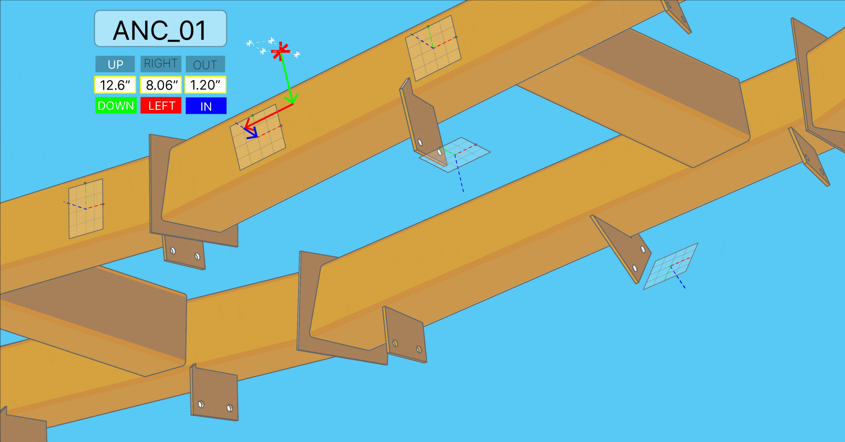


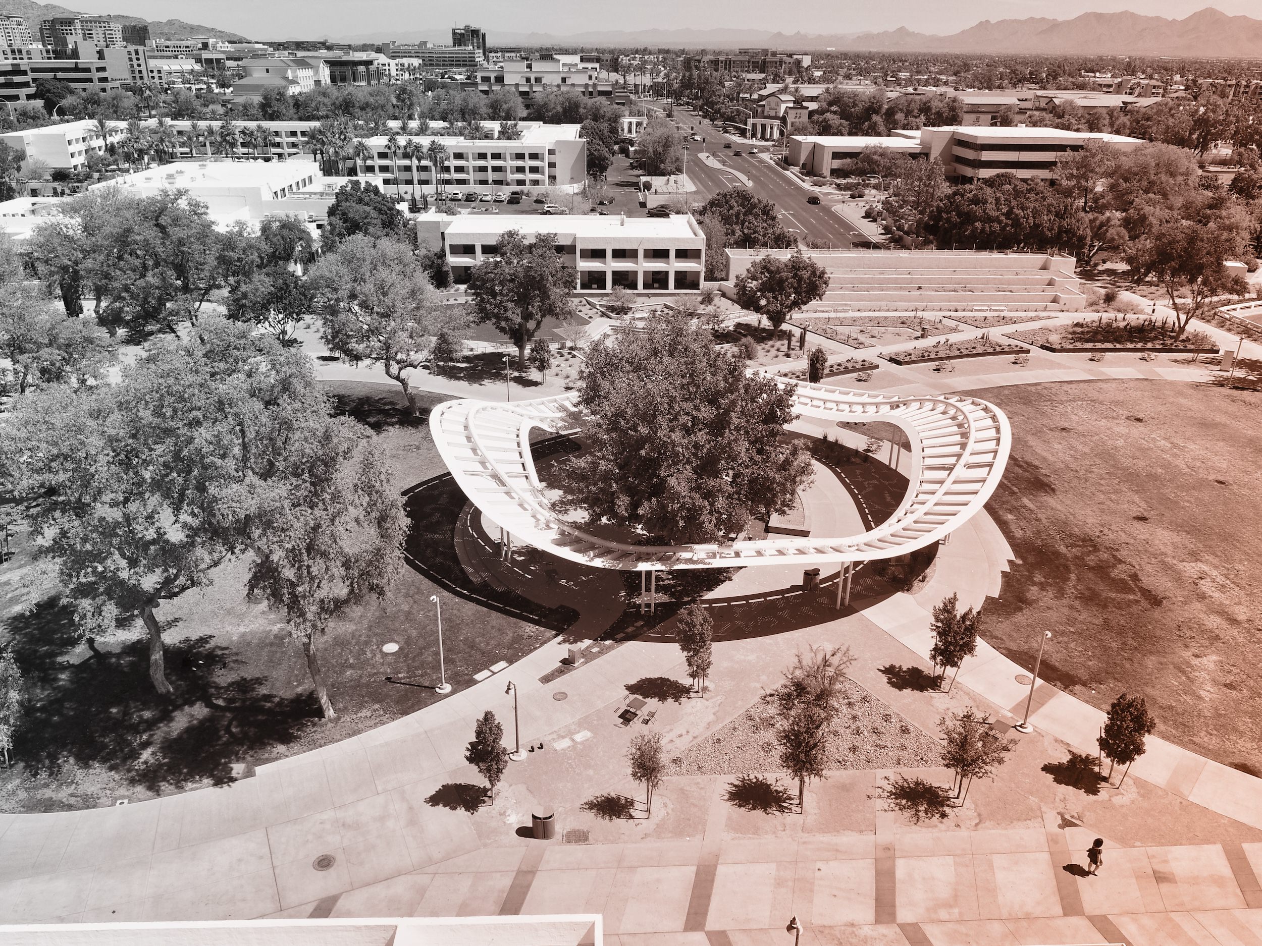
 PHOTO ©️ Parrish Ruiz de Velasco (parrch.com)
 © Fedora Hat Photography
 Photo by Andre Sigur | ARKO

 Ɱ, Creative Commons Attribution-Share Alike 4.0 International license, edited.